Minuet' ...Technical Info
The Technicalities
For those who would like the technical details; there is nothing especially new in Minuet's technology; nothing that hasn't been used before in over 80 years of valve history but the design has been refined. The input stage is a very simple ECC83 (12AX7) twin triode cascode design with an element of negative feedback by virtue of its un-bypassed cathode circuit giving a stage gain of 70 which is directly coupled to an ECC82 (12AU7) in a paraphase long tailed pair phase splitter, this in turn feeds a pair of EL84 Pentode valves running in Class AB Push-Pull in distributed loading and employing cathode bias with 4700 mfd bypass capacitors, like the HT capacitors these are 10 times bigger value than most amplifiers, this ensures adequate current sinking to enable a fast bottom end response. A small amount of negative feedback is taken from the output transformer and fed back to the cathode of the input stage with a small amount of correction selectively added to each amplifier to minimise ringing and overshoot. In addition, a very small amount of negative feedback is selectively added to the cascode input stage in order to minimise the Miller capacitance effect which can promote instability at high frequencies thus the amplifier is stable into any load at any frequency. Brimar valves are used throughout, these being the best available and any future replacements should be of the same make and type. The phonostage consists of two pairs, per channel, of cascode coupled ECC83 (12AX7) valves running at a reduced HT of 200 volts to achieve a very low noise floor and giving a total gain of 140. Very low noise thin film high stability precision resistors are used throughout the phonostage to further reduce the noise level.

Equally Important
The phonostage's equalisation or EQ (often called RIAA) departs from the normal characteristics adopted by most manufacturers. Basically Minuet's EQ system operates in a feedback system using very carefully chosen component values to achieve the response wanted. From the outset it was decided to dispense with the normal RIAA curve and adopt a DBE or 'Design By Ear' approach. Over the course of many months listening to all sorts and variants of music the EQ network was honed to deliver a very open and dynamic sound. In listening tests when compared to the standard RIAA curve there was no contest and the DBE system has been adopted.
Powerfully Minded
The power supplies consist; heaters supply of smoothed DC at 12.6 volts and an HT supply of 380 volts rated at a substantial, for a 10 Watt amplifier, 250mA. All the valve heaters are unusually designed to operate from a single 12.6 volt DC supply in order to reduce the number of wires needed connecting the supply unit to the amplifier. The ECC82 and 83 valves are arranged to operate at 12.6 volts whilst the EL84 output valves, which can only run at 6.3 volts, are arranged in a series parallel formation allowing them to run at 12.6 volts.
The 380 volt HT supply is initially smoothed by a 1000 mfd capacitor with the left and right hand channels then having their supplies separated and individually smoothed each by another 1000 mfd capacitor. Such is the reserve of HT energy that, when switched off, the amplifier will continue to perform for about 30 seconds until the HT is fully depleted. This reserve of energy ensures that when driven to its full 10 Watts output the amplifier's response and speed does not degrade or stumble. Each pair of EL84 output valves are protected by a "wired in" 250mA fuse.
The external power unit contains the mains transformer, fuses, the heaters DC supply, the HT rectifier and surge limiter and the on/off relay which isolates both the HT and heaters supply from the amplifier when off. The mains transformer is run permanently and consumes a fraction of a Watt when the amplifier is in standby. Connection to the amplifier is by a multi cored cable and connector allowing the amplifier and external power unit to be separated, there is a 1.6Amp protection fuse located within the IEC mains socket.

The Layout, Laid Out
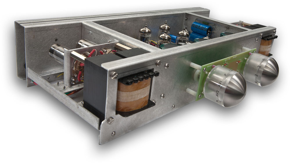
The physical layout of the amplifier is arranged to ensure minimal interaction between components so that heat sensitive parts such as electrolytic capacitors are not subjected to high temperatures. The horizontally mounted output valves, which run very hot, have their own isolated and cooled areas whilst the phonostage is in the centre away from the heat, high voltages and signals.
The input sockets, input selector, volume control and all the associated wiring are contained within a double walled rear panel which isolates these sensitive signal components from the rest of the amplifier. The control shafts are extended out to the front and attached to the knobs by rods running in bearings which take the weight of the heavy solid knobs thus removing mechanical loads from the controls themselves.
Each amplifier is entirely hand built and each optimised for the lowest distortion, ringing and balance based on the initial design criteria of 0.08% maximum total harmonic distortion at a 1kHz driven output level of 10 Watts RMS and a frequency response of better than 10Hz to 40kHz +/- 1dB.
In fact, more representative figures for the production models are; 0.07% THD at 10 Watts and 4Hz to 40kHz +/- 1dB and 4Hz to 60kHz +/- 1.5dB.
Back to the top